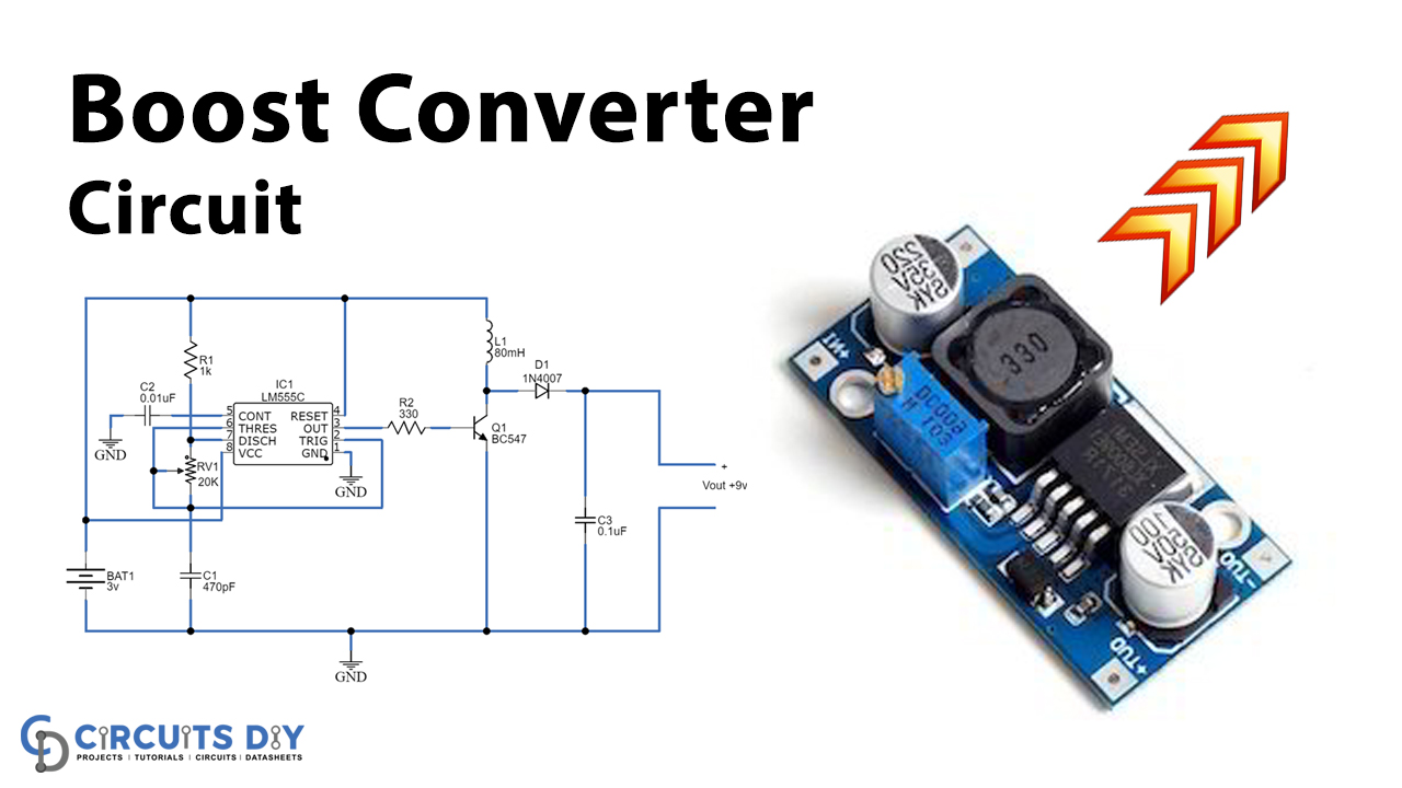
Boost Converter - Circuit Diagram, Working & Waveforms
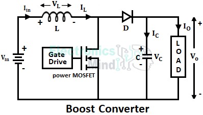
A boost converter is basically a step-up chopper or step-up dc-to-dc converter by which we can obtain an output voltage greater than the input voltage. In other words, boost converters are regulator
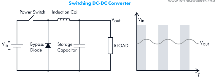
DC-to-DC Converters: Types, Uses, In-Circuit Design, and Firmware
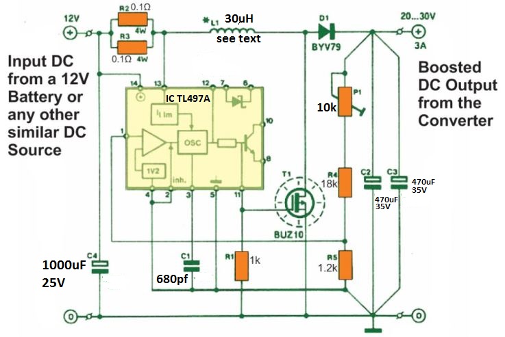
12 V to 30 V High Current Boost Converter Circuit [Variable] - Homemade Circuit Projects

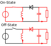
Understanding the Operation of a Boost Converter - Technical Articles
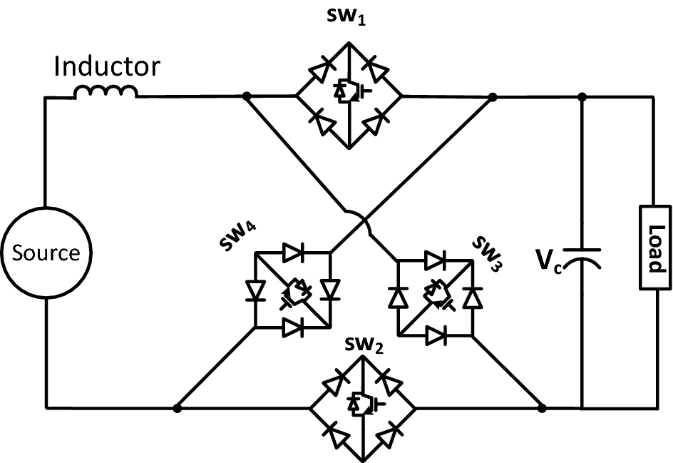
Design, implementation and performance evaluation of multi-function boost converter
Boost Converters
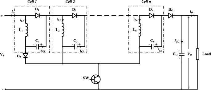
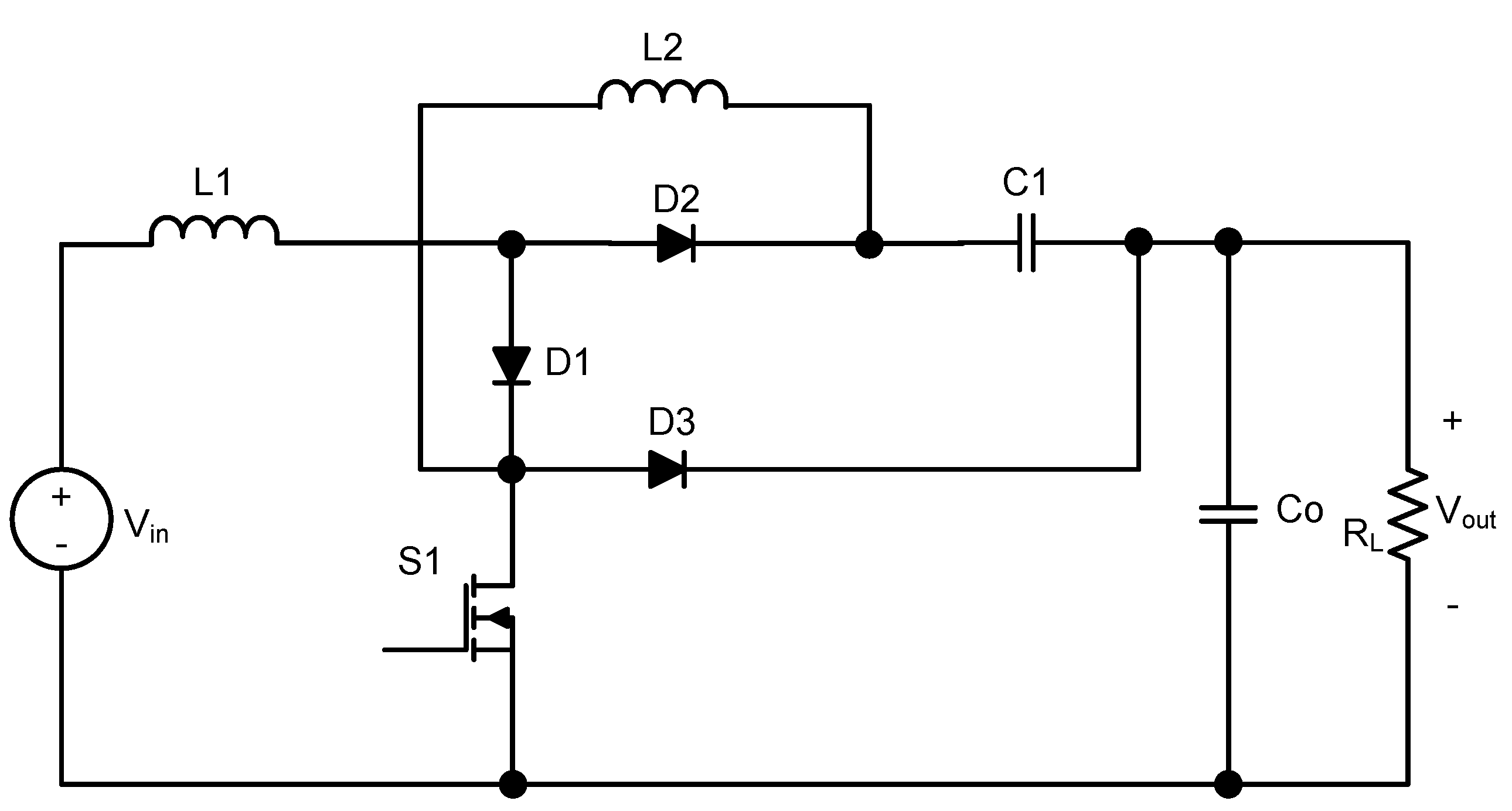
A new extended single-switch high gain DC–DC boost converter for renewable energy applications
Buck Boost Converter Circuit Theory Working and Applications
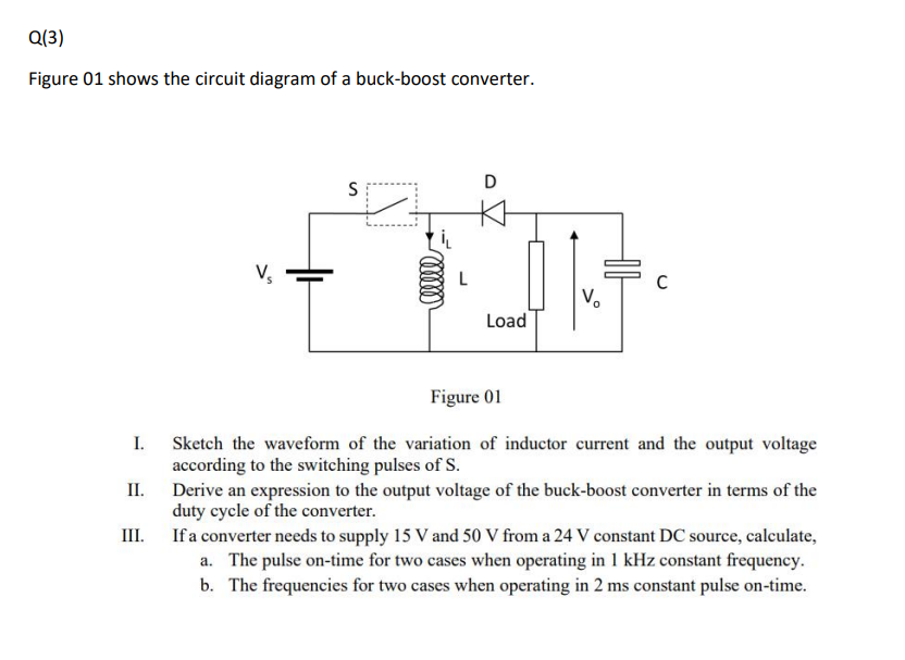
Solved Figure 01 shows the circuit diagram of a buck-boost

Simulation of Boost Converter Using MATLAB SIMULINK.