How to Calculate the Duty Cycle of Boost Converter

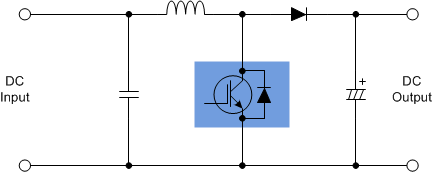
The inductor waveform is the key on how to calculate the duty cycle of boost converter. You can get direct equation for boost converter duty cycle formula from different sites but here I will discuss how it is derived. Meanwhile, a familiar boost converter schematic is shown in Figure 1. The inductor of the boost
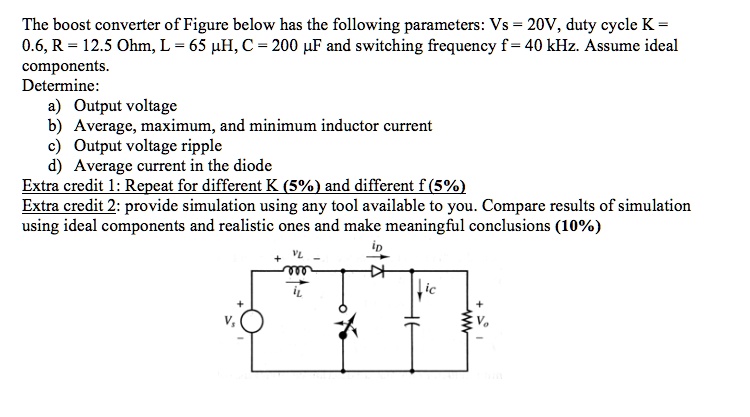
SOLVED: The boost converter of Figure below has the following parameters: Vs = 20V, duty cycle K = 0.6, R = 12.5 Ohm, L = 65 uH, C = 200 uF, and

Get more boost from your boost converter - EDN Asia

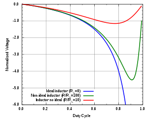
Effect of duty cycle on (L,C) design of buck-boost converter.
Output voltage vs. duty cycle of the boost converter circuit for
Buck–boost converter - Wikipedia
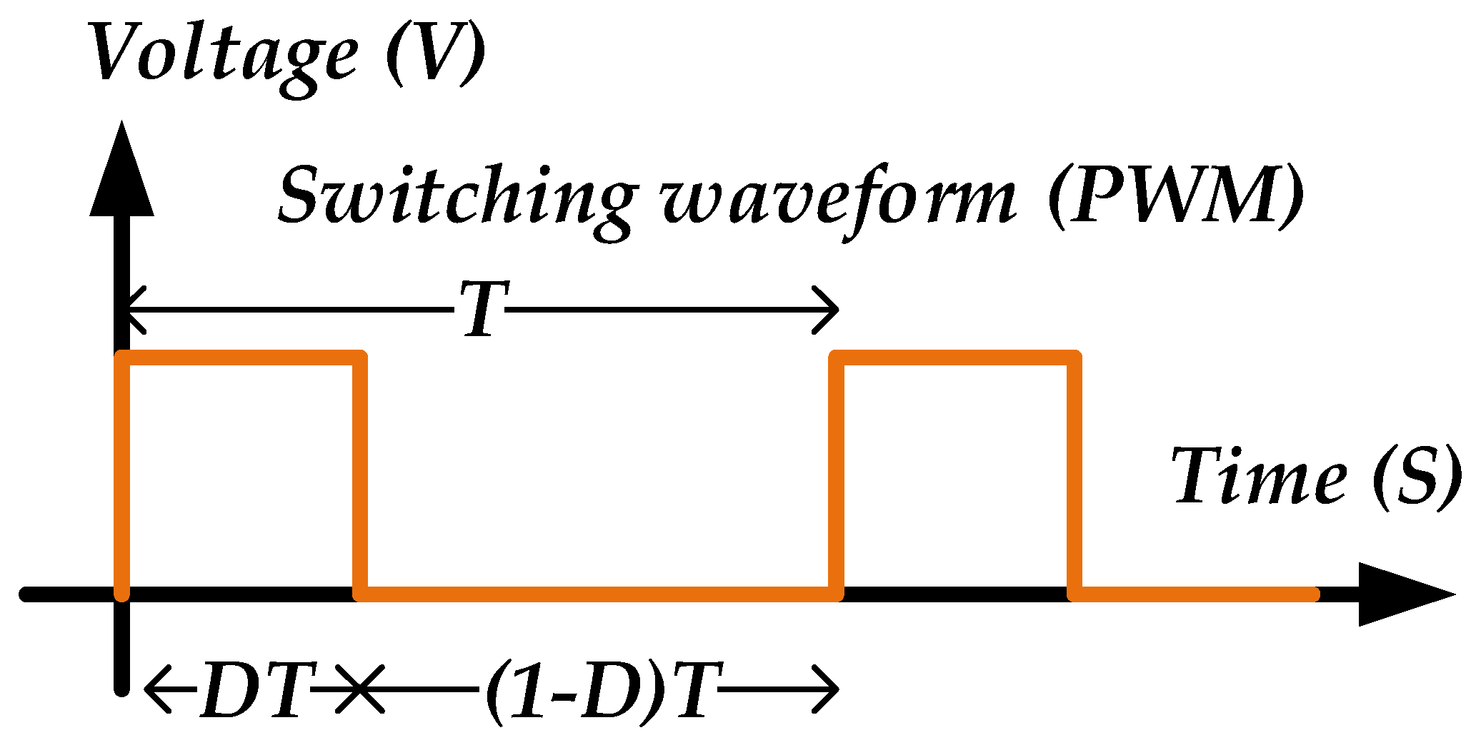
Duty Cycle - GeeksforGeeks
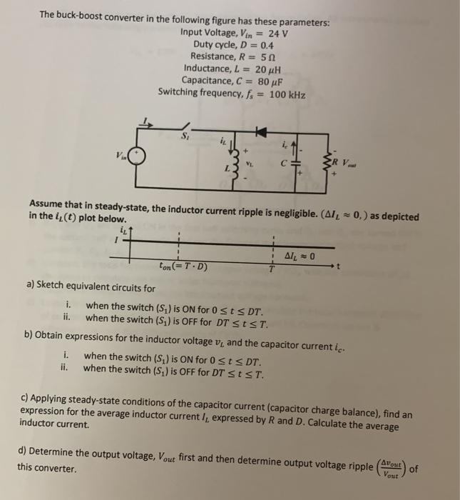
Solved The buck-boost converter in the following figure has
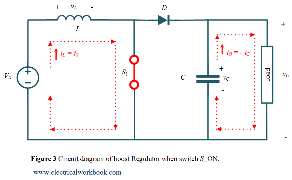
Boost Regulator Average Output Voltage Expression Derivation and Duty Cycle - ElectricalWorkbook

How to Calculate the Duty Cycle of Boost Converter

Boost Converter: Design, Circuit, Equations & More
Electronics, Free Full-Text
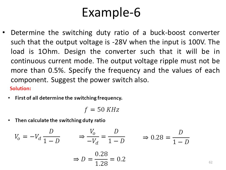
Power Electronics Lecture-10 D.C to D.C Converters (Choppers) - ppt video online download
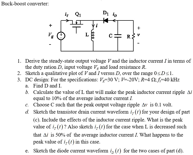
SOLVED: Buck-boost converter: Q1 D1 D1 in it A 1. Derive the steady-state output voltage V and the inductor current I in terms of the duty ratio D, input voltage V- and